Simulation of fuel spray motion and combustion in
two-stroke diesel
with side injection system
The results of calculation of
spray motion and fuel distribution in two-stroke marine diesel with side
injection are presented below in comparison with published experimental data
[3]. Calculations of sprays tip penetration in large marine engine and in small
diesels were performed using same equations without recalibration [2].
Design of combustion chamber and sprayers is presented in fig. 1. Every sprayer
has 4 holes with diameter 0.75 mm..
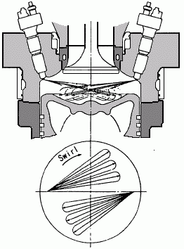 |
Engine: Mitsubishi UEC 45 LA
D = 450 mm
S = 1350 mm
RPM = 158; injector: 4 x 0.75
Angles of holes in above view:
500 , 350, 90, -10
.gif) |
Fig. 1. Side Injection Combustion System
Piston bowl design was specified using DIESEL-RK interface (fig. 2.) This
interface allows specifying any piston bowl, edit them, saving piston bowls in
data base.
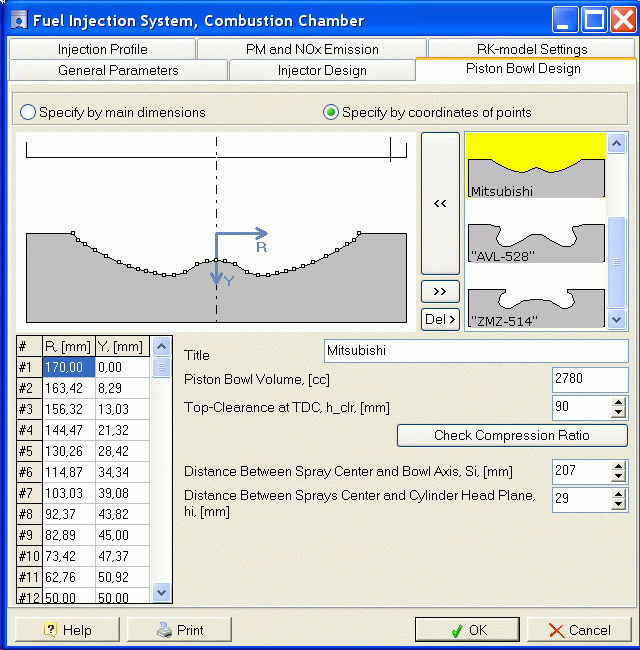
Fig. 2. DIESEL-RK window for piston bowl specification.
Results of simulation of fuel sprays evolution are presented in fig. 3.
Experimental apparatus as well as results of calculation using CFD software are
published by H.Nakagawa, Y.Oda, S.Kato, M.Nakashima and M.Tateishi [3]. Fig. 3
shows results of Fuel Spray Visualization code operation. Above view is very
close to experimental image as well as to image obtained by CFD simulation.
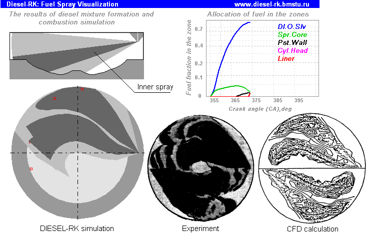
Fig.3. Results of simulation of fuel sprays evolution with DIESEL-RK software
in comparison
with published CFD simulation and experiment [3].
Notations for curves on fuel allocation diagram:
Dl.O.Slv - is a fuel
fraction allocated in
Dilute Outer Sleeve of the free spray and in Dilute Outer Surroundings of Near-Wall Flow.
Spr.Core - is a fuel
fractionallocated in
Dense Core of the free spray.
Pst.Wall - is a fuel fractionallocated in the Near-Wall Flow.
Cyl.Head - is a fuel fractionsettled on cylinder
cover surface.
Liner
- is a fuel fractionsettled on cylinder liner surface.
The swirling gas velocity distribution diagram is presented in fig. 4. Data of
fig. 3 correspond with maximum swirl intensity. Figure 5 shows sprays tip
penetration curves obtained by DIESEL-RK simulation in comparison with
experiment [3]. Calculated curves are close to experimental ones but some
difference exists. By the way, the same difference is presented in comparison of
CFD simulation results with the experiment (fig. 6). The simulation with
DIESEL-RK software was performed using equations and same empiric coefficients
that were used at simulation of fuel spray motion for small diesel with nozzles
bore 0.145 mm [2]. It verifies the universality of the spray evolution model of
DIESEL-RK software
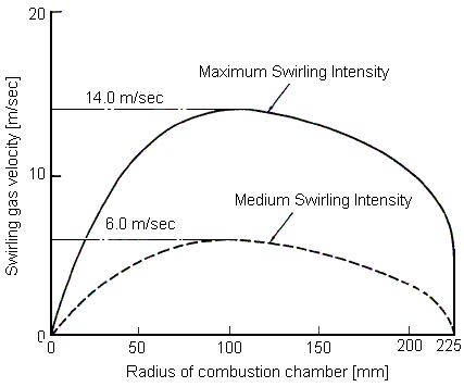
Fig. 4. Swirling Gas Velocity Distribution.
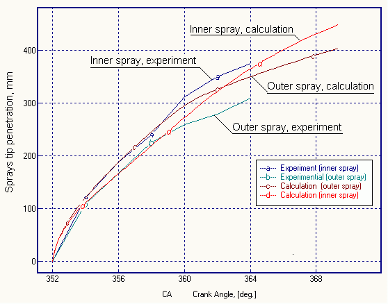
Fig. 5. Sprays tip penetration curves obtained by DIESEL-RK simulation in
comparison with experiment [3].
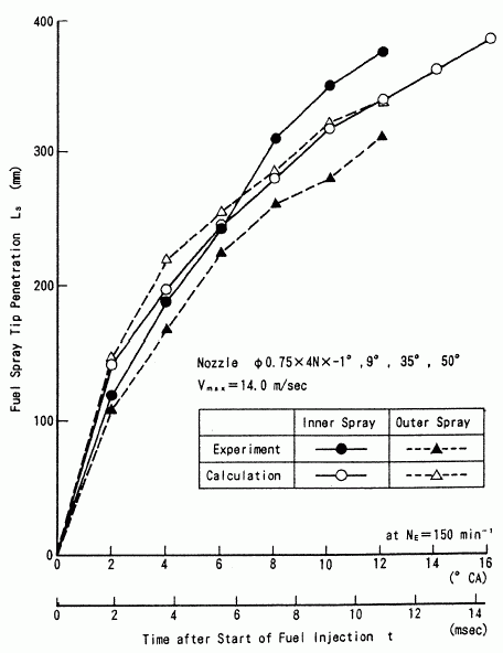
Fig. 6. Sprays tip penetration curves obtained by CFD calculation [3] in
comparison with experiment [3].
For simulation of combustion in DI diesel the RK-model has been developed and
implemented in full cycle engine simulation software. The multi-zone diesel
spray combustion model divides spray into zones and simulates redistribution of
fuel in zones during sprays evolution. Denotation of zones of diesel fuel spray
is presented in figure 7. Each zone has own conditions of evaporation and
burning and these conditions are uniform within a whole zone. While spray is
free (before impingement) there are only 3 characteristic zones: 1 - Dense Axial
Core, 2 - Dense Forward Front, 3 – Dilute Outer Sleeve. The Near-Wall Flow (NWF)
being formed after impingement is inhomogeneous in structure, density and
temperature. After wall impingement, a new set of zones is taken into account: 4
- Axial Conical Core of a NWF, 5 - Dense Core of a NWF on a piston bowl surface,
6 - Dense Forward Front of a NWF, 7 - Dilute Outer Surroundings of NWF. Together
with above listed ones, when fuel hits the cylinder liner and the cylinder head
surface, the corresponding zones are taken into account too.
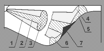
Fig. 7. The scheme of fuel spray zones.
Notations:
1 - Dilute Outer Sleeve of free spray.
2 - Dense axial Core of free spray.
3 - Dense forward front.
4 - Dilute Outer Surrounding of a Near-Wall Flow.
5 - Dense Core of a Near-Wall Flow on a piston surface.
6 - Forward front of a Near-Wall Flow.
7 - Axial conical core of a Near-Wall Flow.
If NWF forward front reaches the cylinder head surface as shown in fig. 7, a
fuel fraction settled in the cylinder head zone is defined depending top piston
clearance and current piston position. If NWF spot reaches the cylinder liner, a
fuel fraction in the liner zone is defined too. If two adjacent Near-Wall Flows
intersect, the fuel fraction in the intersection zone is defined depending on
area of intersection.
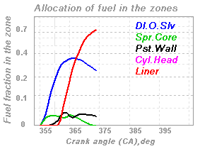
Figure 8 shows calculated with DIESEL-RK distribution of fuel in the zones for
inner (a) and outer (b) sprays during ones evolution in swirled air of running
two-stroke Mitsubishi UEC 45 LA diesel.
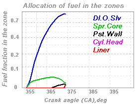
a) Inner spray |
b) Outer spray |
Fig. 8. Results of simulation of fuel distribution in running engine for
inner (a) and outer (b) sprays during ones evolution.
The main difference between inner and outer sprays evolution and fuel
allocation is that the main fuel fraction of outer spray hits on cylinder liner
surface (red curve in fig. 8, a). The main fuel fraction of inner spray
distributes in cylinder volume (blue curve in fig. 8, b) with the best
evaporation conditions by analogy with four-stroke medium speed diesel engines.
The hitting of fuel on cylinder liner surface of four stroke engine causes
increase of fuel consumption and smoke emission due to very bed evaporation
condition on the cold surface of cylinder liner. In the two-stroke low-speed
engine the temperature of cylinder top side is about 600 K (see fig. 9), because
it is a part of cylinder cover. This temperature is enough to provide good
evaporation conditions in this zone, so the low fuel consumption of the engine
persists. Typical surface temperatures of cylinder liner cover and piston crown
in two-stroke engine is presented in fig. 9 [4].
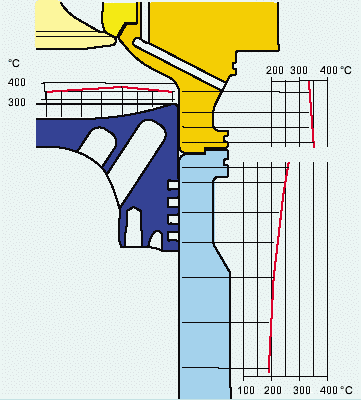
Fig. 9. Typical surface temperatures of the liner, cover and piston crown in
two-stroke engine [4].
3D results of spatial sprays
evolution simulation with description of characteristic zones. The visualization
tool here allows optimization of nozzles orientation to minimize a negative
effect from sprays interaction
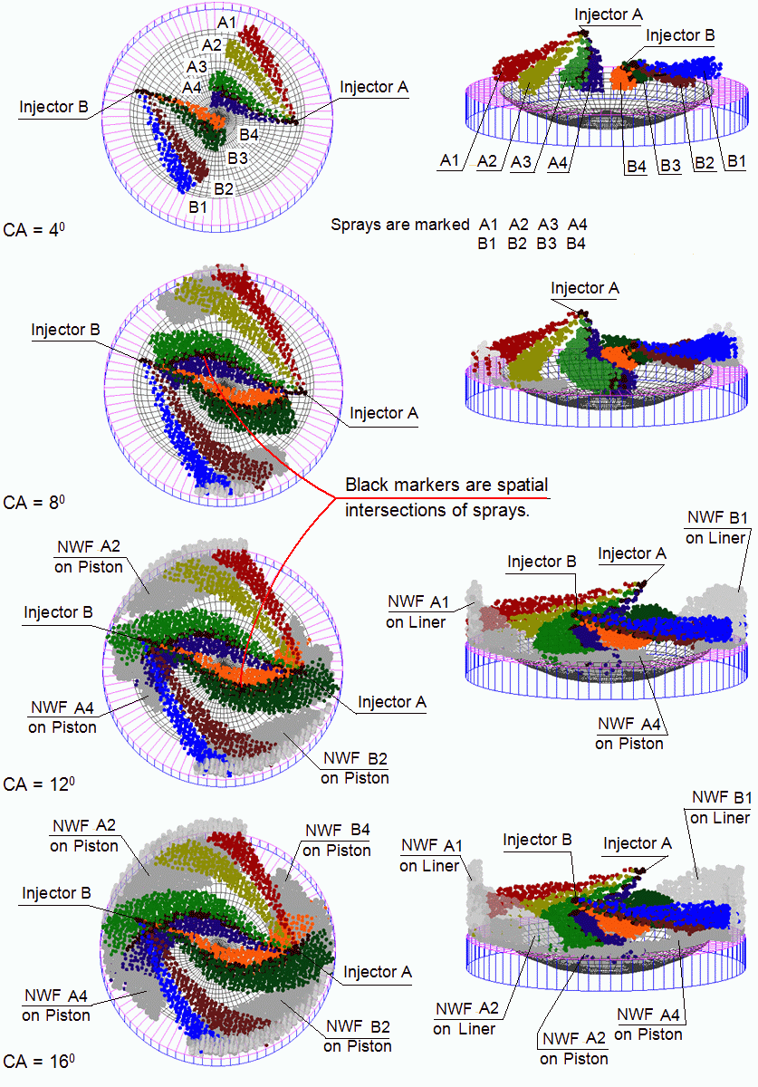
Fig. 10. 3D results of spatial sprays evolution simulation
with description of characteristic zones
CONCLUSION
DIESEL-RK software allows research of combustion and mixture formation in four-
and two-stroke diesels with:
• any kinds of piston bowl design and sprayers location,
• a few of sprayers located in periphery of cylinder,
• multiple injection,
• different kinds of swirl epures.
REFERENSES
- A.S. Kuleshov: “Model for predicting air-fuel mixing, combustion and
emissions in DI diesel engines over whole operating range”, SAE Paper No
2005-01-2119, 2005.
- A.S. Kuleshov: "Use of Multi-Zone DI Diesel Spray Combustion Model for
Simulation and Optimization of Performance and Emissions of Engines with
Multiple Injection", SAE Paper No 2006-01-1385, 2006.
- H.Nakagawa, Y.Oda, S.Kato, M.Nakashima and M.Tateishi: "Fuel Spray Motion in
Side Injection Combustion System for Diesel Engines", International Symposium
COMODIA 90, pp. 281-286, 1990.
- Kaspar Aeberli: “Marketing the Sulzer RT – flex50”, Marine news, No 2, pp.
16-18, 2004.
To page
"Applications"


|
