Simulation of mixture formation, combustion and NO emission
in truck diesel with different strategies of injection.
To verify correctness of the
diesel models
assumptions, the RK-model [1, 2] has been tested to fit the engine with different
strategies of injection: single, double and triple. To test the software, the
data by Bakenhus and Reitz [3] were used. They tested the single-cylinder
Caterpillar D/S = 137/165 mm engine at different injection timing values and for
different injection strategies, see Fig. 1.
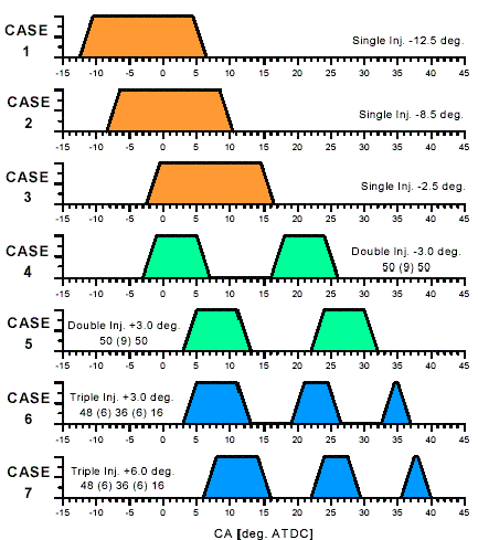
Figure 1. Nomenclature and schematic of injection profiles by Bakenhus and Reitz
[3].
The piston bowl shape and fuel sprays evolution of the engine
are shown in Fig. 2.
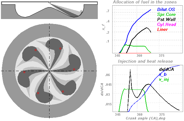
Figure 2. Piston bowl shape and fuel sprays evolution of the engine. Injector: 6
x 0.259mm, RPM=1600.
Notations for curves on fuel allocation diagram:
Dilut.OS - is a fuel fraction allocated in
Dilute Outer Sleeve of the free spray and in Dilute Outer Surroundings of Near-Wall Flow;
Spr.Core - is a fuel allocated in
Dense Core of the free spray;
Pst.Wall - is a fuel fraction allocated in the Near-Wall Flow;
Cyl.Head - is a fuel fraction settled on cylinder
cover surface;
Liner
- is a fuel fraction settled on cylinder liner surface.
Notations for curves on Injection and heat release diagram:
dx/dCA is a heat release rate; x_b
is a heate release fraction; v_inj is
an injection velocity.
For simulation of combustion in DI diesel the RK-model has been developed and
implemented in full cycle engine simulation software. The multi-zone diesel
spray combustion model divides spray into zones and simulates redistribution of
fuel in zones during sprays evolution. Denotation of zones of diesel fuel spray
is presented in figure 3. Each zone has own conditions of evaporation and
burning and these conditions are uniform within a whole zone. While spray is
free (before impingement) there are only 3 characteristic zones: 1 - Dense Axial
Core, 2 - Dense Forward Front, 3 – Dilute Outer Sleeve. The Near-Wall Flow (NWF)
being formed after impingement is inhomogeneous in structure, density and
temperature. After wall impingement, a new set of zones is taken into account: 4
- axial conical core of a NWF, 5 - dense core of a NWF on a piston bowl surface,
6 - dense forward front of a NWF, 7 - dilute outer surroundings of NWF. Together
with above listed ones, when fuel hits the cylinder liner and the cylinder head
surface, the corresponding zones are taken into account too.
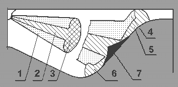
Fig. 3. The scheme of fuel spray zones.
Notations:
1 - Dilute Outer Sleeve of free spray.
2 - Dense axial Core of free spray.
3 - Dense forward front.
4 - Dilute Outer Surroundings of a Near-Wall Flow.
5 - Dense Core of a Near-Wall Flow on a piston surface.
6 - Forward front of a Near-Wall Flow.
7 - Axial conical core of a Near-Wall Flow.
If NWF forward front reaches the cylinder head surface as shown in fig. 7, a
fuel fraction settled in the cylinder head zone is defined depending top piston
clearance and current piston position. If NWF spot reaches the cylinder liner, a
fuel fraction in the liner zone is defined too. If two adjacent Near-Wall Flows
intersect, the fuel fraction in the intersection zone is defined depending on
area of intersection.
The autoignition delay period has been predicted for each fuel portion during
multiple injection. Fuel of second, third and later portions was injected after
TDC with great delay and into a surrounding with a large burnt gas fraction.
These specific conditions make the use of classic formulas for calculation of
the autoignition delay period incorrect. The equation providing a good agreement
between simulation results and measurements for various type engines was derived
in the paper [2] on the basis of experimental data processing.
The calculated heat release curves for single, double and triple injection were
obtained and compared with the experimental data [3] in Figs. 4, 5. The
injection profiles are marked in the figures with a bold line.
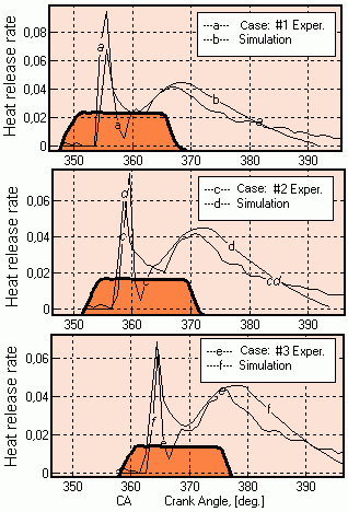
Figure 4. Experimental heat release rates for single injection obtained by
Bakenhus and Reitz [3] and calculated with RK-model ones. Cases: 1, 2, 3.
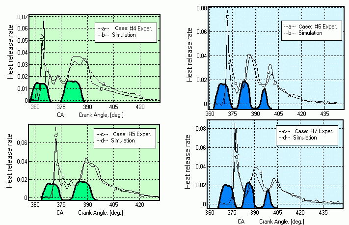
Figure 5. Experimental heat release rates for double and triple injections
obtained by Bakenhus and Reitz [3] in comparison with calculated by RK-model
ones.
Cases: 4 (injection timing: 3 deg. BTDC); 5 (injection timing: 3 deg. ATDC).
Cases: 6 (injection timing: 3 deg. ATDC); 7 (injection timing: 6 deg. ATDC).
All calculations were carried out with identical calibration of the RK-model.
The calculation results of NOx emission for each case are given in Fig. 6 as
compared with the experimental data. The experimental data by Bakenhus and Reitz
[3] are presented in g/kW h.
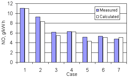
Figure 6. Comparison between measured and calculated NOx emission in diesel with
different injection strategies.
CONCLUSION
It has been shown in that the DIESEL-RK software allows the engine
thermodynamic parameters, power and efficiency as well as NOx emission to
be predicted with sufficient accuracy for diesels with any kinds of multiple injection
strategies
REFERENSES
- A.S. Kuleshov: “Model for predicting air-fuel mixing, combustion and
emissions in DI diesel engines over whole operating range”, SAE Paper No
2005-01-2119, 2005.
- A.S. Kuleshov: "Use of Multi-Zone DI Diesel Spray Combustion Model for
Simulation and Optimization of Performance and Emissions of Engines with
Multiple Injection", SAE Paper No 2006-01-1385, 2006.
- Marco Bakenhus and Rolf D. Reitz: “Two-Color Combustion Visualization of
Single and Split Injections in a Single-Cylinder Heavy-Duty D.I. Diesel Engine
Using an Endoscope-Based Imaging System”, SAE Paper No. 1999-01-1112, 1999.
To page
"Applications"


|
