"Fuel Spray Visualization" code
The Fuel Spray Visualization code is a program of
visualization of a mixture formation in a diesel. This code is included in the DIESEL-RK.
The code is intended for visual mapping of calculation results obtained at
simulation of the engine.

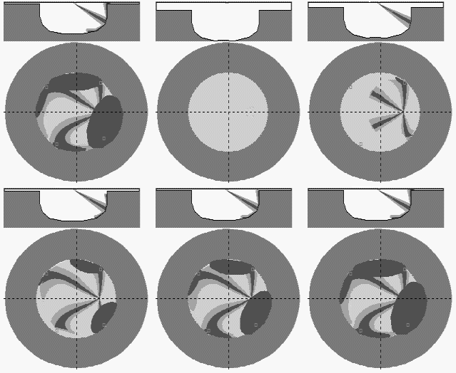
The code displays on the screen the moving image of evolution
of fuel sprays and their near wall flows (NWF) and also the diagrams of allocation of
the sprayed fuel in characteristic zones. The program allows step by step observing:
- the evolution of fuel sprays and their NWF in a combustion chamber in view of effect of
swirl;
- the deformation of sprays by swirl;
- the forming of NWF depending on angle of spray and wall impingement;
- the evolution of NWF under effect of a swirl and NWF interaction among themselves;
- the curves of fuel allocation in the characteristic zones;
- the curves of injection rate and heat release.
Example: Visualization of mixture formation in tractor diesel CMD
 |
Allocation of fuel in the zones
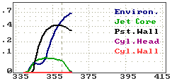 |
On image of longitudinal section of spray and on diagram: "Allocation of
fuel in the zones" the data of one selected spray are presented. |
Injection and heat release
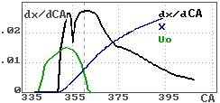 |
On image of a combustion chamber plan and on diagram:
"Injection and heat release" the data of all sprays are presented. |
|
The animation of fuel sprays evolution is carried out on
a basis of calculation of their trajectories and deformation under influence of an air
swirl. The forms of stains of wall surface flows are calculated depending on the values of
angles of collision of jets with walls and effect of swirl.
On the image "Longitudinal section of spray" the
combustion chamber and selected spray are represented. The secant surface passes through
an axis of the spray before its collision with a wall, and further along the straight line
which is tangent to the axis.
Notations of curves in diagrams
Allocation of fuel in the zones

| Environ.
|
is a curve of fuel fraction allocated in the dilute outer
sleeve of free spray,
in front of free spray and in dilute outer surrounding of NWF. There are best conditions
of evaporation in this zone. |
| Jet Core |
is a curve of fuel fraction allocated in a core of free spray. There are
very poor conditions of evaporation in this zone. |
| Pst.Wall
|
is a curve of fuel fraction allocated in a core of near wall flow on a
surface of piston bowl. Conditions of evaporation in this zone a depend on surface
properties and temperature. |
| Cyl.Head
|
is a curve of fuel fraction allocated on surface of cylinder head.
Conditions of evaporation in this zone are not very good. |
| Cyl.Wall
|
is a curve of fuel fraction allocated on surface of cylinder liner. There
are very poor conditions of evaporation in this zone. |
Injection and heat release
 |
dx/CA is a curve of heat
release rate.
X
is a curve of heat release.
Uo
is a curve of injection velocity. |
Observing the evolution of NWF in a map of plan
of combustion chamber it is possible to see an intersection of NWF spots among themselves.
Creation of a large area of NWF crossing causes a decrease of evaporation rate and
heat release. The amount of fuel allocated in the intersection zone is registered in the
common table of results. Allocation of fuel in these zones causes a reallocation of a
summarized amount of fuel of all jets among the characteristic zones. Parts of fuel
allocated in environment of all sprays and in normal NWF of all sprays are diminished. It
causes a deceleration of combustion of fuel, increase of a specific fuel consumption and
emission of soot. (See. Simulation
of interaction of jets with an air swirl and walls.)
At the end of calculation the data of allocation of fuel
in the zones are output for each spray and for all sprays as a whole. Usage of these data,
integral parameters of an engine and the Fuel Spray Visualization code makes it
possible not only to compare
different variants of constructions among themselves and to estimate their advantages
and disadvantages, but also to select optimum combinations of a combustion chamber shape
and fuel sprays orientation which allow achieve a small level of harmful materials
emission and specific fuel consumption.
The example of similar research is represented in site: Numerical research of
possibility to decrease a level of NOx emission of diesel engine by means of
optimization of the piston bowl shape, fuel sprays orientation, ... (The measures
providing a lowering of NOx emission by 43 % and simultaneous reducing of fuel consumption
are designed.)
To achieve a good mixture formation, fast
combustion and low level of fuel consumption each spray has to be directed so that the
maximum amount of fuel should be allocated in zones with good conditions of evaporation. It is
first of all, zone of dilute surrounding of a spray and, to a lesser degree, core of a
NWF. It is
necessary to avoid allocation of fuel in zones of intersection of NWF, and also the
settlement of fuel on a cylinder liner and on a cylinder head, especially, if the head is
made of aluminum alloy and has low temperature. For fast evaporation it is necessary to
provide a small diameter of drops. To achieve a low level of NOx emission it is necessary
to diminish self-ignition delay, to diminish amount of fuel burning down by volumetric
mechanism at high local temperature. The software DIESEL-RK and built-in Fuel Spray
Visualization code allow optimization the piston bowl shape, swirl intensity, fuel
sprays orientations, compression ratio, injection characteristic, etc. to coordinate these
opposite tendencies and to find the favorable compromises.
You can observe on your computer a moving image of evolution
of fuel sprays and their wall surface flows in combustion chambers of different diesels.
The Fuel Spray Visualization code together with data kit can be downloaded free from the web.
To Home page


|
