Simulation of diesel combustion at split injection
Split injection of fuel in diesel is one of
the effective way of NO emission decrease. At split fuel supply the injection is divided
on 2, 3 and more stages followed step by step. Optimization of fuel fraction in pilot
injection as well as optimization of delay between injection stages are the problems,
which can be solved with DIESEL-RK software. The RK-model of diesel combustion takes
into account evolution of fuel sprays in a charge, wherein combustion of a pilot fuel
portion has taken place already.
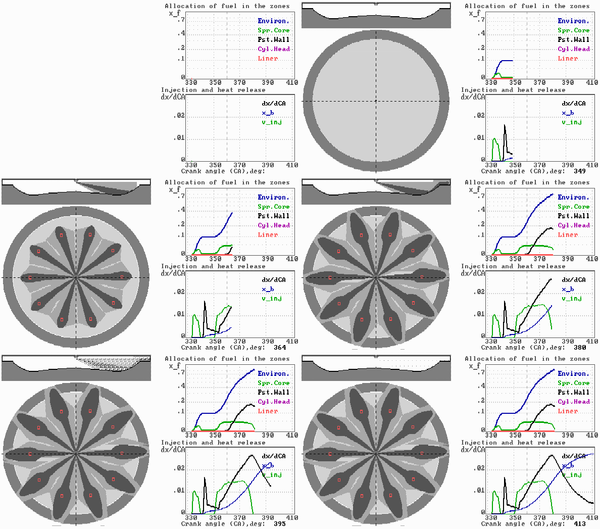
In this page some results of calculation of
mixture formation and combustion in medium-speed diesel with double stage injection are
presented. The pilot injection fraction is about 11 % of full fuel supply. Fuel Spray
Visualization shows that burning of pilot fuel occurs after its injection. The
main injection begins during afterburning of pilot fuel.

 |
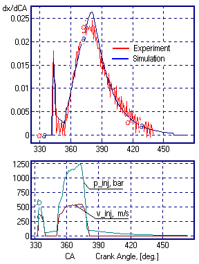
The heat release diagram gives the comparison between calculated and
measured data (experimental red curve was obtained in Kolomna plant).
Diagrams of injection pressure p_inj and injection velocity v_inj.
The maximum injection pressure is about 1200 bars.
|
The picture of mixture formation shows evolution of
sprays in a shallow piston bowl of the locomotive diesel.
The spray, meeting with the piston surface at the acute
angle, forms narrow and prolate in radial direction wall surface flow. This
configuration of spots allows the increase number of nozzles or use a swirl, whereas in a
conventional, deep combustion chamber these cause overintersection of wall surface flows
and degradation of engine characteristics.
On the other hand, a shallow piston bowl requires precise
orientation of injector nozzles to avoid hit of fuel on a cylinder liner.
To page
"Applications"


|


