Matching the piston bowl shape and spray angle for the
locomotive diesel
The simulation technique described earlier has been used for
matching the piston bowl shape and spray angle of the locomotive diesel. The
engine has the following parameters: D/S = 318/330, RPM=750 and BMEP=10 bar.
The injector of the engine has 8 nozzles with a diameter of 0.36 mm each.
Geometries of the piston bowl considered in this investigation are presented
in Fig. 1. The spray angle a was varied from 65 up
to 85 degrees for each bowl geometry and for part and full load modes of
operation. The results of calculations of the spray evolution process and fuel
distribution in the diesel cylinder for a part load operation (35% capacity,
RPM=400) are shown in figures 2 and 3. In these figures mf liner is the fuel
fraction reaching the cylinder liner at the end of the spray evolution process.
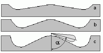
Figure 1. Geometries of the piston bowl.
For part load operation all piston bowl geometries result in
the engine’s operation with similar parameters for the spray angle
a between 65 and 75 degrees. But when
a exceeds 80 degrees then the specific fuel
consumption also increases for middle and shallow piston bowl geometries. The
high fuel consumption is the result of fuel reaching the cylinder liner in the
combustion chambers. Due to the low level temperature of the cylinder liner
surface the evaporation conditions in this zone are poor. On the other hand
the deep bowl blocks and prevents the fuel spray reaching the cylinder liner.
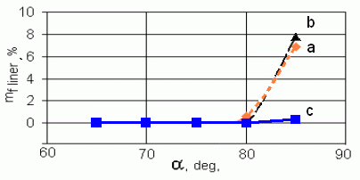
Figure 22. The fuel fraction which has reached the cylinder liner at the end
of spray evolution process at part load conditions.
If sprays reach a piston bowl wall at the angle less than 150
degrees than further movement of the fuel along the walls occurs at lower
velocity (which is much less than that of a free spray) and fuel does not
reach the cylinder liner.
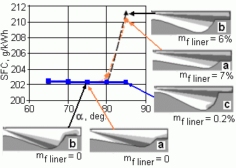
Figure 3. Effect of the piston bowl shape and spray angle on
the SFC at part load conditions.
At part load mode the application of all geometries of the
piston bowl result in the same engine performance parameters. If
a is less than 75 degrees then there is sufficient
space for sprays and near-wall flow evolution process since the mass of the
injected fuel is small and the injection duration is short.
At full load conditions the portion injected fuel is greater and the duration
of injection is longer. Calculations show that for such conditions three bowl
geometries provide different engine efficiencies, see Fig. 4. In this figure
mf cross is a fuel fraction allocated in the zones of NWF overlaps at the end
of the spray evolution process.
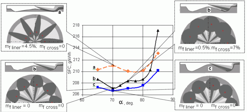
Figure 4. Effect of spray angle a
on SFC for different piston bowls at full load of locomotive diesel. a)
Shallow piston bowl; b) Middle piston bowl; c) Deep piston bowl.
The shallow piston bowl geometry results in lower efficiency
because fuel reaches the cylinder liner at all values of the spray angle
a. Zones of near-wall flows formed after reaching
bowl walls at the low angle have the form elongated in the radial direction
and the high velocity of movement along the walls. Fuel in such zones reaches
the cylinder liner. The fraction of fuel which reaches the cylinder liner is
4.5 % even in case when the spray angle is 75 degrees. Shallow piston bowls
provide advantage only in large engines with a high distance between the
sprayer and the cylinder liner as well as in engines with the high boosting
pressure because the high density of air reduces the spray penetration
distance and as result of this, fuel does not reach the cylinder liner. For
such conditions the width of each NWF zone is reduced and more nozzles can be
used for each injector. The increase in the number of nozzles also allows us
to shorten the injection period. The last also allows to decrease the
near-wall flow zones length in the radial direction and to prevent fuel from
reaching the cylinder liner surface. Finally, the shorter injection period
results in the shorter combustion process and higher engine efficiency.
Deep piston bowls have advantages if the engine has a low boosting pressure
and fuel sprays have the long penetration length due to the small air density
and the long injection duration. In this case the high piston crown provides a
desirable form of near-wall flow zones. Location of the spot where spray
reaches the wall and the spray incidence angle have to be such that to form
NWF zones evolved in both radial and tangential directions in order to prevent
fuel from reaching the cylinder liner. Additionally, extreme overlapping of
near-wall flow zones from adjacent sprays should be avoided.
To home page


|
